Categories
Categories

| Price: | US $ 0.74/Piece |
|---|---|
| Min Order: | 1000/Piece |
| Pay Type: | L/C,T/T,D/P |
| Prod Model: | ISL1208IU8Z-TK |
|---|---|
| Category: | Real Time Clock |
| Function: | Clock, Calendar, Alarm |
| Rtc Bi: | Serial (I2c) |
| Date Format: | Dw:Dm:M:Y |
| Time Format: | Hh:mm:Ss |
| Rtc Memory Capacity: | 2 B |
| Power Supply Voltage: | 5.5 V Max |
| Power Supply Voltage Min: | 2.7V |
| Operation Temperature Range: | -40~85 |
Low Power RTC with Battery Backed SRAM
Description
The ISL1208 device is a low power real time clock with timing and crystal compensation, clock/calendar, power fail indicator, periodic or polled alarm, intelligent battery backup switching and battery-backed user SRAM. The oscillator uses an external, low-cost 32.768kHz crystal. The real time clock tracks time with separate registers for hours, minutes, and seconds. The device has calendar registers for date, month, year and day of the week. The calendar is accurate through 2099, with automatic leap year correction.
Features
• Real Time Clock/Calendar
- Tracks Time in Hours, Minutes, and Seconds
- Day of the Week, Day, Month, and Year
• 15 Selectable Frequency Outputs
• Single Alarm
- Settable to the Second, Minute, Hour, Day of the Week,
Day, or Month
- Single Event or Pulse Interrupt Mode
• Automatic Backup to Battery or Super Cap
• Power Failure Detection
• On-Chip Oscillator Compensation
• 2 Bytes Battery-Backed User SRAM
• I2C Interface
- 400kHz Data Transfer Rate
• 400nA Battery Supply Current
• Same Pin Out as ST M41Txx and Maxim DS13xx Devices
• Small Package Options
- 8 Ld MSOP and SOIC Packages
• Pb-Free Plus Anneal Available (RoHS Compliant)
Applications
• Utility Meters
• HVAC Equipment
• Audio/Video Components
• Set Top Box/Television
• Modems
• Network Routers, Hubs, Switches, Bridges
• Cellular Infrastructure Equipment
• Fixed Broadband Wireless Equipment
• Pagers/PDA
• POS Equipment
• Test Meters/Fixtures
• Office Automation (Copiers, Fax)
• Home Appliances
• Computer Products
• Other Industrial/Medical/Automotive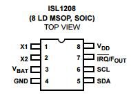
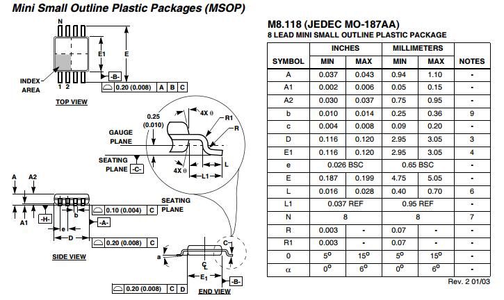
NOTES:
1. These package dimensions are within allowable dimensions of
JEDEC MO-187BA.
2. Dimensioning and tolerancing per ANSI Y14.5M-1994.
3. Dimension "D" does not include mold flash, protrusions or gate
burrs and are measured at Datum Plane. Mold flash, protrusion
and gate burrs shall not exceed 0.15mm (0.006 inch) per side.
4. Dimension "E1" does not include interlead flash or protrusions
and are measured at Datum Plane. Interlead flash and
protrusions shall not exceed 0.15mm (0.006 inch) per side.
5. Formed leads shall be planar with respect to one another within
0.10mm (0.004) at seating Plane.
6. "L" is the length of terminal for soldering to a substrate.
7. "N" is the number of terminal positions.
8. Terminal numbers are shown for reference only.
9. Dimension "b" does not include dambar protrusion. Allowable
dambar protrusion shall be 0.08mm (0.003 inch) total in excess
of "b" dimension at maximum material condition. Minimum space
between protrusion and adjacent lead is 0.07mm (0.0027 inch).
10. Datums and to be determined at Datum plane
11. Controlling dimension: MILLIMETER. Converted inch dimensions
are for reference only.


